
3D PRINTING GUIDE
FDM 3D printing tolerances: designing parts that fit
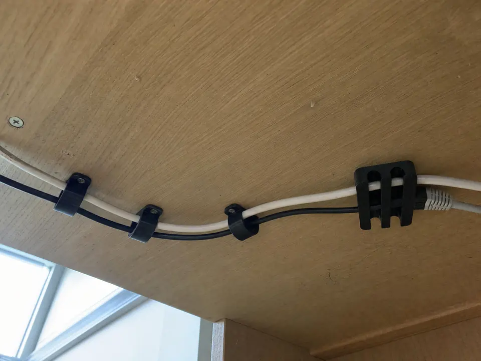
Illustrative image; not a documented customer order.
A CAD model can specify a perfect fit, but a printed component has real dimensional variation. Material shrinkage, geometry, print orientation, nozzle size and process settings all affect the result.
Nominal dimensions versus real dimensions
A 10 mm hole in a CAD model may not measure exactly 10 mm after printing. Holes, thin features and internal corners can be especially sensitive to process conditions. Do not assume that two parts designed with zero clearance will assemble freely.
Choose the type of fit first
A loose sliding fit, a tight push fit and a snap-fit connection serve different purposes and require different clearances. State whether an element must move freely, remain secure or be easy to remove.
Holes, screws and inserts
Screw holes and mounting features need suitable clearances and enough material around them. Depending on the application, drilling, tapping or threaded inserts may be preferable to relying on the raw printed hole.
Clips and flexible connections
Snap-fits depend on material flexibility, layer orientation and the geometry of the bending area. Sharp corners and thin roots can create stress concentrations. A reference prototype is strongly recommended.
Test rather than guessing a universal tolerance
There is no single clearance that works for every printer, material and geometry. A small tolerance test or initial sample can establish what works for a particular project.
What to include in your order
Provide the mating component's key dimensions, required motion, acceptable play and the intended installation method. This gives the workshop a practical basis for assessing fit.